Fatigue life prediction of gas tungsten arc welded AISI 304L cruciform joints with different LOP sizes
Fatigue life prediction of gas tungsten arc welded AISI 304L cruciform joints with different LOP sizes
Abstract
Fatigue life evaluations have been carried out on gas tungsten arc welded (GTAW) load-carrying cruciform joints of AISI 304L stainless steel with lack of penetration (LOP) using conventional S-N and crack initiation-propagation (I-P) methods. The crack process normally comprises two major phases: (1) the crack initiation life (Ni ): and (2) the crack propagation life (Np). The local stress-life approach is used to estimate the crack initiation life and a fracture mechanics approach for predicting crack propagation life of welded joints. Constant amplitude fatigue tests with stress ratio, R 0 were carried out using 100 KN servo-hydraulic DARTEC universal testing machine with frequency of 30 Hz. An automatic crack monitoring system based on crack propagation gauges was used to find the crack initiation and propagation data during fatigue process. The predicted lives were compared with the experimental values. It was found that the fatigue lives of the joints with LOP=2 mm for 6 mm thickness plate were relatively higher than those for the joints with other LOP sizes. Test results were compared with BS 5400: part 10 (now replaced by BS 7608) design curve. 2002 Published by Elsevier Science Ltd.
Keywords: Stainless steel; Gas tungsten arc welding (GTAW); Cruciform joints; Lack of penetration (LOP); Fatigue life
1. Introduction
Stainless steels are widely used in the chemical pro- cesses and power generation industries. However, increasingly they are also being considered for structural applications, for example, in facading and transportation industries. Stainless steels offer the advantages over con- ventional structural steels where painting or other cor- rosion protection coatings would not be necessary. Many applications in the structural areas involve welded components, which have to be designed to avoid fatigue failure. Though considerable fatigue data exist for welded joints in structural carbon steels [1–4], there are very sparse design data for stainless steel welded joints [5]. Further, the fatigue crack growth behaviour in stain- less steel weldments appears to be least investigated. In the present work, an attempt has been made to fill up this lacunae through a detailed investigation on the fatigue performance of load carrying transverse fillet welded cruciform joints of AISI 304L stainless steel with differ- ent LOP sizes.
There are two types of fatigue cracking in fillet- welded joints: (a) root cracking and (b) toe cracking. In welded cruciform joints, the lack of penetration (LOP) occurs in the joint due to the lack of access to the root. The structures in which such joints used are often sub- jected to fatigue loading. This may result in the initiation of fatigue cracks at the LOP tip as well as from the toe region, which depends on the LOP size, fillet geometry and leg length. One of the formulae for stress intensity factors for the root of cruciform welded joints containing lack of penetration was presented by Frank and Fisher using a finite element method [6] and then improved in BS 7910 [7]. Frank has also analyzed the fatigue lives of cruciform joints [8]. Other investigators have also studied the fatigue behavior of cruciform welded joints of carbon steels failing from the root (LOP) [9–12].
Usami and Kusumoto determined a solution for the maximum principal stress intensity factor by considering both KI and KII in the case of cruciform joints with root crack [11]. The stress intensity factors KI and KII of cru- ciform joints were calculated by the finite element method [13]. The fatigue limit and the direction of crack propagation under mixed load loading are well expressed by the maximum principal stress criterion. In this analy- sis, the cracks were considered to be grown in Mode I type and the Frank’s stress intensity factor solution for cruciform joints with LOP [6] is used here. Fatigue life prediction of cruciform welded joints is very complex, costly and time consuming. This is due to its complex joint geometry, number of stress concen- tration points and heterogeneous weld metal property making the joint. Traditionally, the fatigue life of the joint for structural applications followed the S-N type of approach covered by BS 5400: part 10 and IIW [14]. For critical structural applications, both initiation and propagation behavior are equally important for the pur- pose of safety. The linear elastic fracture mechanics (LEFM) approach which estimates the crack propagation life (Np) was used to calculate the total life (NT) of welded joints. However, the LEFM approach always gave conservative results of NT when compared with those of modern weldments experimental data [15–17]. These results led to the crack initiation–propagation model (IP model) in which the crack initiation life (NI) was added to the weldment total life [18]:
This investigation has been carried out to study the influence of LOP sizes on fatigue life of gas tungsten arc welded cruciform joints, failing from root. The fatigue lives of these joints were predicted using the I- P model.
2. Experimental
The material used was an AISI 304L austenitic stain- less steel in the cold rolled form of 6 mm thickness. These plates were cut into the required sizes by shearing. The initial joint configuration in the case of load-carry- ing cruciform joint is obtained by securing the long plate (300 × 100 mm2 ) and stem plate (300 × 50 mm2 ) in a cruciform position by tack welding keeping in a fixture. Subsequently, fillets were made between the long plate and stem plate by laying weld metal using the GTAW process with filler wire 308L. The double pass technique was used with argon as the shielding gas. All the four fillets forming the joint were made, leaving a non-fused gap between the pair of fillets. This gap, called LOP, was controlled by providing proper root faces obtained by a prior machining process, known as beveling. This enabled the joints to have different LOP lengths after
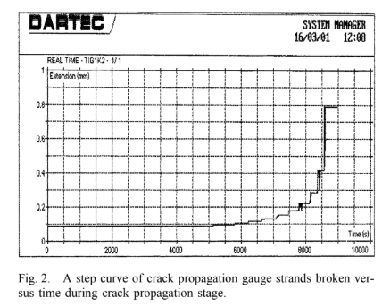
welding. The dimensions of the cruciform joint shown in Fig. 1 considered in the present investigation are given as: 2a 2, 3, 4 and 6 mm, 2W 14 mm, L 4 mm, Tp 6 mm and q 30° (concave fillet). All the neces- sary care was taken to avoid joint distortions and the joints were made without applying any clamping forces. After welding, the fatigue samples were cut into the required sizes (20 mm) using a power saw. The cut samples were again machined for better surface fin- ishing. Welds were tested by X-ray radiography for their soundness. Fatigue experiments with a stress ratio R=0 were car-ried out in a 100 kN servo-hydraulic DARTEC universal testing machine with a frequency of 30 Hz. For each condition, 12–16 specimens were tested. The specimens were tested to complete failure or to an endurance of 2 million cycles (in some cases, it was 3 million cycles), if there was no evidence of fatigue cracking. In all tests, it was ensured that the crack always started in the LOP and propagated through the weld metal. An automatic crack monitoring system based on the crack propagation gauges was used to find the crack initiation and propagation data during the fatigue process with an accuracy of 0.25 mm. The crack propagation
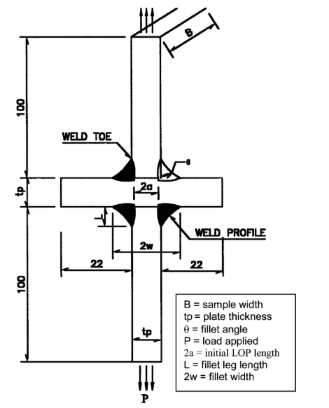
Fig. 1. Schematic diagram of load carrying transverse fillet welded cruciform joint with LOP defect (all dimensions in mm).
ducted for various stress levels and the variations in crack length (a) with the corresponding number of cycles (N) were obtained.
3.1. Crack propagation analysis:
The fracture mechanics analysis for most structural steels is based on the Paris power law [19], da/dN C(K) m (2) where da/dn is the crack growth rate, K is the stress intensity factor (SIF) range, and C and m are Paris con- stants. Eq. (2) can be normalized and adopted for cruci- form joints, in the form given below d(2a/2W) dN C(K) m sm sm 2W (3) where s is the nominal stress range at the base plate,
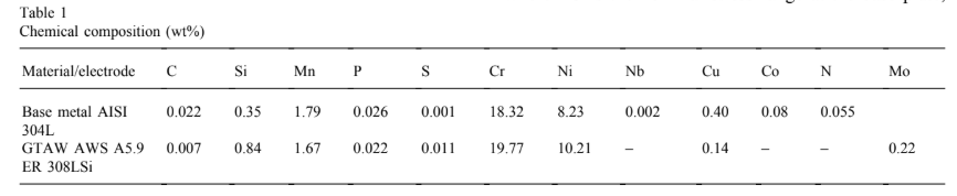
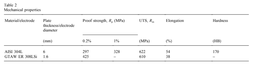
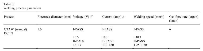
gauges consist of a number of resistor strands connected in parallel. This is bonded to a specimen at the tip of the root gap through a connector circuit and progression of the crack through the gauge pattern causes successive open circuiting of the strands, resulting in an increase in total resistance. The output is amplified and a step curve of strands broken versus time can be obtained in the computer (Fig. 2). The chemical composition and mech- anical properties of base metal and filler metal are given in Tables 1 and 2. The welding process parameters used to fabricate the joints are presented in Table 3.
3. Results and discussion
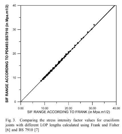
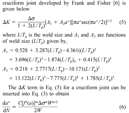
The LOP size will influence the fatigue life of cruci- form joints. Fatigue crack growth experiments were con- ‘a’ is half of the LOP size, and ‘W’ is half of the fillet width as shown in Fig. 1. After re-arranging the equation da∗ dN C 2 ·[f ∗(a)]m·smW(m/2)1 (4) where f ∗(a) is the normalized SIF range which is K/s·W1/2, and a∗ is the normalized crack length a/W. The crack growth rate, da/dn for crack propagation stage was calculated. For all calculations, the ASTM E- 647 guidelines were followed. The stress intensity fac- tors for cruciform joints were calculated using Frank and Fisher [6] and BS 7910 [7] and the values are compared in Fig. 3. Since the authors found negligible variation, it is proposed to use Frank’s formulae for calculating SIF range. The polynomial expression for SIF range (K), for a crack at the weld root of a load carrying
The terms can be rearranged for integration to give
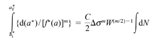
where a∗ i is the initial defect size after the number of cycles necessary for crack initiation (NI) and a∗ f is final defect size at failure. The above equation can also be expressed as:
where Ip is the value of the integral in Eq. (7) for the number of crack propagation cycles leading to failure (Np). It was found that the value of integration Ip is a function of crack length a∗ with respect to crack growth exponent values (m). It can be seen that for all values of m, the function
falls on a single straight line against Ip [20]. The straight-line relationship can be expressed by the follow- ing empirical equation:
where the constants, r 0.16 and h 0.84 depend on the crack geometry. Rearranging Eq. (8) gives
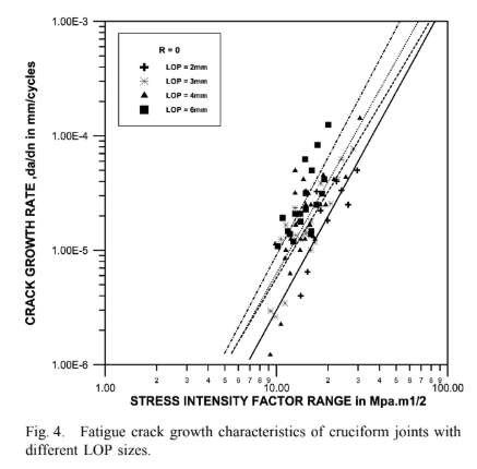
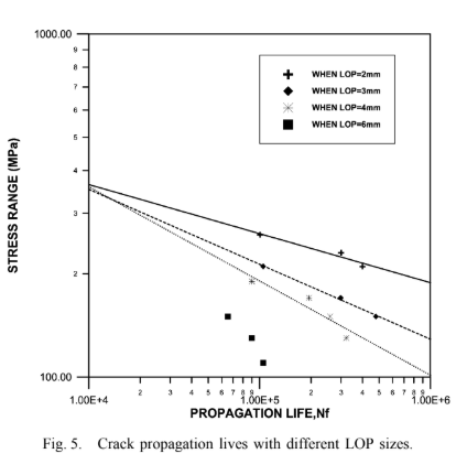
The relationship between the SIF range (K) and the corresponding crack growth rate, da/dn on a log–log scale in terms of best fit line is shown in Fig. 4 for all the cases. The data points mostly correspond to the second stage of the sigmoidal relationship of the Paris equation. The crack growth rate is found to be the same (slope is almost same) in all the cases and the Paris con- stants ‘m’ and ‘C’ are given in Table 4. The intercept ‘C’ varies with respect to LOP sizes. The propagation lives of the joints are shown in Fig.
5. It can be seen that the joints with LOP 2 mm show large propagation lives and the joints with LOP
6 mm show less propagation lives. This is due to the fact that the crack has to propagate a longer distance in the weld metal when LOP 2mm and smaller distance
when LOP 6mm.
3.2. Crack initiation analysis
The crack initiation life ‘NI’ was evaluated experimen- tally using the crack initiation criteria [21–24]. Here, in our investigations the initiation criterion has assumed the number of cycles required to grow 0.5 mm length of crack in excess of its original LOP length under parti- cular stress range. To estimate NI, a local stress-life or strain-life approach is commonly used [16,18,24]. The simplest form of this approach is
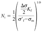
where s/2 is the stress amplitude, sf is the fatigue strength coefficient, b is the fatigue strength exponent, sm is the mean stress and Kf is the fatigue notch factor. This model is based on the Basquin equation with the Morrow mean stress correction. The prediction method also requires that the fatigue notch factor (Kf) be calcu-
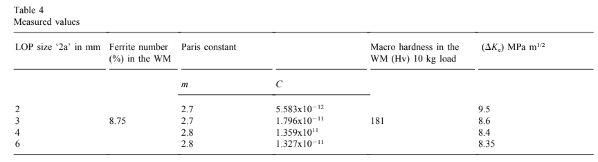
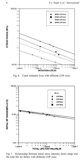
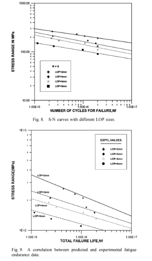
lated. The fatigue notch factor for load-carrying cruci- form joints with different LOP sizes is calculated accord- ing to Yung and Lawrence [25]. From Fig. 6, it is clear that in a load carrying cruciform joint with LOP defect, the joints with LOP 2 mm have larger fatigue initiation life for 6 mm thickness plate. Fig. 7 shows the relationship between the initial SIF range (Ki ) and the number of cycles to failure (Nf). This relation is similar to the S-N relation giving the endurance SIF (Ke) simi- lar to the endurance fatigue limit. The value of the endur- ance SIF corresponding to 2 million cycles is given in Table 4. However, it should be noted that the endurance value obtained is for the case R 0. The S-N curves in all the cases are compared in Fig. 8. It can be seen from the results presented that the LOP size has a stronger effect on the fatigue life.
3.3. Total fatigue life analysis
To predict the total fatigue life of the cruciform joints, it is necessary to account for the crack initiation life (Ni)
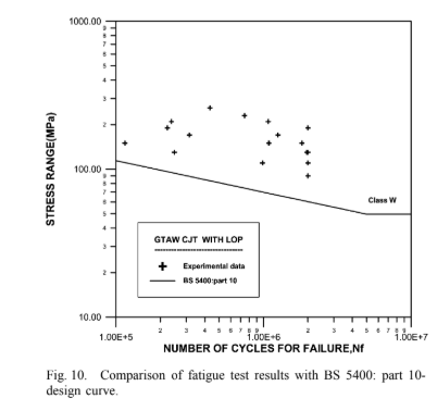
and crack propagation life (Np) separately. The total fatigue life is evaluated using Eq. (1). The accuracy of the predicted life is tested by comparing the predicted fatigue life data with the experimental data and the scat- ter diagram is shown in Fig. 9. Although relatively high residual stresses were likely to occur in the welds before cutting up the plates, they were relieved by the slicing operation [26]. The fatigue test results of these joints were compared with the BS 5400: part 10 (now replaced by BS 7608) design curve for cruciform joints with LOP and shown in Fig. 10. The results show good correlation with the standards.
4. Conclusions
From the experimental investigations carried out to study the fatigue crack growth behavior of gas tungsten arc welded load carrying cruciform joints of AISI 304L with different LOP sizes, the following conclusions have
been drawn:
- The two-stage approach, including both the fatigue crack initiation and propagation phases, enables one to estimate total fatigue lives in the life regime of 105 to 2 million cycles, which agree within a factor of 2 with experimental data for cruciform welded speci- mens failing at the LOP.
- The crack growth behaviour of load carrying cruci- form joints with LOP follows the Paris equation.
The relationship between the initial stress intensity factor range (Ki ) and the number of cycles to failure (Nf) can be presented in a similar way to that of the conventional S-N curve.
In this experiment, the cruciform joints with LOP 2 mm show superior fatigue properties com- pared to other LOP sizes for the 6 mm thickness plate.
The fatigue life of load carrying cruciform joints with LOP for the GTAW process was predicted with reasonable accuracy. The results show good corre- lation with the BS 5400: part 10 design curve.
Acknowledgements
The work was done at I.I.T., Madras. The financial support from the Avesta Polarit Research Foundation, Sweden, as well as the supply of materials are grate- fully acknowledged. References
[1] Gurney TR, Maddox SJ. A re-analysis of fatigue data for welded joints in steel. Welding Res. Int. 1973;3(4):1–54.
[2] BS 5400. Steel concrete and composite bridges, code of practice for fatigue, part 10. BSI; 1980.
[3] HSE (Health And Safety Executive—Offshore Installations). Guidance on design, construction and certification. 4th ed; 1990
[4] BS 5500. Specification for unfired fusion welded pressure vessels. BS1; 1991
[5] EURO INOX. Design manual for structural stainless steel; June 1994.
[6] Frank KH, Fisher JW. Fatigue strength of fillet welded cruciform joints. J. Struct. Div. 1979;105:1727–39.
[7] British Standards Institution. Guidance on methods for the acceptance of flaws in structure. PD 6493, BS 7910, appendix
J; 2001.
[8] Frank KH. The fatigue strength of fillet welded connections. PhD thesis, Lehigh University; Oct 1971.
[9] Knight JW. Some basic fatigue data for various types of fillet welded joints in structured steel. Welding Institute members report 9/1976/E; 1976.
[10] Maddox SJ. Assessing the significance of flaws in welds subjects to fatigue. Weld. J.W.R.S. 1974;53(9):401–9.
[11] Usami S, Kusumoto S. Fatigue strength at roots of cruciform, tee nd lap joints (Fracture mechanics analysis of fatigue strength of welded joints, Ist report). Trans. Japan Welding Soc. 1978;9(1):3–10.
[12] Motarjemi AK, Kohabi AH, Ziaie AA, Mantegui S, Burdekin FM. Comparison of the stress intensity factor of T and cruciform welded joints with different main and attached plate thickness. Engineering. Fract. Mech. 2000;65:55–66.
[13] Miyata H, Shida S, Kusumoto S. The simple method of evalu- ation of stress intensity factor using the finite element method. In: Proceedings of the Symposium on Mechanical Behaviour of Materials; 1974. p. 63–81.
[14] Hobbacher A. Recommendations on fatigue of welded compo- nents. IIW Doc.XIII-1539-95/XV-845-95; 1988.
[15] Lawrence FV. Estimation of fatigue-crack propagation life in butt welds. Welding Res. 1973;52:212s–20.
[16] Skorupa M. Fatigue life prediction of cruciform joints failing at the weld toe. Welding Res. 1972;71:269s–75.
[17] Ferreira JA, Branco CM. Fatigue analysis and prediction in fillet welded joints in the low thickness range. Fat. Fract. Eng. Mater. Struct. 1990;13:201–12.
[18] Lawrence FV, Mattos RJ, Higashida Y, Burk JD, Estimating the fatigue crack initiation life at welds, ASTM STP 648. Philadel- phia: ASTM; 1978. p. 134–58.
[19] Paris PC, Erdogan F. A critical analysis of crack propagation laws. J. Basic Eng. 1963;85:528–38.
[20] Guha B. A new fracture mechanics method to predict the fatigue life of welded cruciform joints. Eng. Fract. Mech. 1995;52(2):215–29.
[21] Jack R, Price AT. The use of crack initiation and growth data in calculation of fatigue lives of specimen containing defects. Metal Const. 1971;3:416–9.
[22] Testin RA, Young JY, Lawrence FV, Rice RC. Predicting the fatigue resistance of steel weld metals. Weld. Res. Suppl. 1987;4(93):93s–8.
[23] Zheng X. A further study on fatigue crack initiation life-mechan- ical model for fatigue crack initiation. Int. J. Fatigue 1986;8(1):17–21.
[24] Bhuyan G, Vosikovsky O. Prediction of fatigue crack initiation lives for welded plate T-joints based on the local stress-strain approach. Int. J. Fatigue 1989;11(3):153–9.
[25] Yung JY, Lawrence FV. Analytical and graphical aids for the fatigue design of weldments. Fatigue Fract. Engng. Mater. Struct. 1985;8(3):223–41.
[26] Gurney TR. Fatigue of welded structures, 2nd ed. UK: Cambridge University Press, 1979.